- 您现在的位置:买卖IC网 > Sheet目录180 > 2866242 (Phoenix Contact)UPS 24VDC 40A DIN RAIL
Uninterruptible Power Supply Unit for Universal Use – QUINT-DC-UPS/24DC/40
5.9. Remote Shutdown ("Remote", Fig. 12)
The device has a UPS remote shutdown function for
speci ? c shutdown.
3 14 D
O K C +
Remote shutdown must be deactivated for the device
to switch to buffer mode in the event of a supply voltage
failure.
13
14 O D C
K +
+ +
3 14 D
11 14 O D C
21 OK C +
1 R1 +
R2
m R2
Al 32 Re
33
ar m
Ba
OF
ON F
Mo t.-
Ch t.-
ge
Al
Ba a .-
t -C o
ha de
rg
QU de
Op tp
ar
Al
Mo rge
t.-
AP
Ba Ch
U
Remote Shutdown Off
? The "Remote shutdown R1" and "Remote
shutdown R2" terminal points are short circuited
(e.g., with a plug-in bridge) OR
The "Remote shutdown R2" terminal point is
supplied with a 24 V DC voltage
? The QUINT-DC-UPS switches to buffer mode in the
event of a supply voltage failure
Remote Shutdown On
? The "Remote shutdown R1" and "Remote
shutdown R2" terminal points are not connected
? All LEDs are off
? The QUINT-DC-UPS does not switch to buffer mode
in the event of a supply voltage failure, instead the
V
0,2
13
A
11 23 R1
13
K
31 + +
2 –
2 2
31
de Ba
ar
ar m
B
. t M
e
21 ot e
8
I
Or p u
In e
Ou
m
de
P
a
Figure 12
device is shut down. When the supply voltage is
reapplied, the battery module is charged and the
device remains off until remote shutdown is
deactivated.
? Connected loads are supplied as long as the supply
voltage is present
6. Setting Options on the Device
40
pu
+
Ba at.-
t.-C Mo
ha de
rg
we
OK
[m ax 0,5 1
Ba
ele 0
[A t
rvic
≤ 3
≥ 1 ,2
ar
Al
od
at. -M h arge
t.-
Ba OK
er
Po
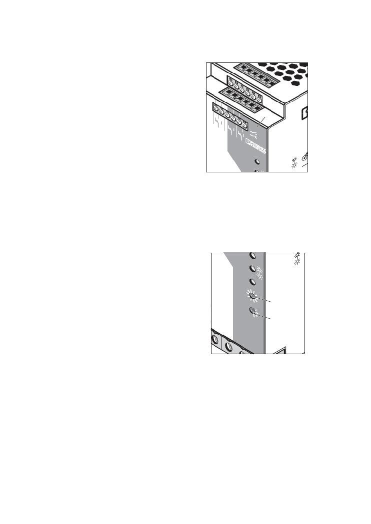
(Fig. 13)
6.1. Buffer Time Setting
Buffer mode can be exited after a prede ? ned time
has elapsed or by external
shutdown (see 6.9).
If the device is to be shut down after a speci ? c time
has elapsed, the time can be set via the
selector switch § on the front of the device.
When the supply voltage is reapplied, the device
can switch to buffer mode again.
V
ut
O A
t
B
rm
e
Po
r In
t
m
in] ∞
30
t.-S 2
c
h]
2
3
5
15 10
Se
7
2
e
,4
m
B C
w
§
$
In
e
6.2. Battery Module Setting
Before startup, the capacity of the battery module
–
Ba
+
t t e
ry
used must be set on the device via the selector switch
$ . When replacing the battery, the selector switch
must be set to "Service" (see also 6.7).
PHOENIX CONTACT page 8 of 9
–
Figure 13
发布紧急采购,3分钟左右您将得到回复。
相关PDF资料
2866255
PWR SUPPLY 5A 100-240AC 48VDC
2866297
PWR SUPPLY 8A 100-240AC 10-15VDC
2866336
PWR SUPPLY 100W 100-240AC 24VDC
2866446
POWER SUPPLY 1.3A 100-240AC 24DC
2866640
UPS 24VDC 2A
2866653
POWER SUPPLY 1.5A 24VDC
2866679
POWER SUPPLY 5A 85-264AC 48DC
2866682
POWER SUPPLY 10A 48VDC
相关代理商/技术参数
28-6625-10
功能描述:IC 与器件插座 DIP HEADERS 28 PINS SCREW MACHINE CONT RoHS:否 制造商:Molex 产品:LGA Sockets 节距:1.02 mm 排数: 位置/触点数量:2011 触点电镀:Gold 安装风格:SMD/SMT 端接类型:Solder 插座/封装类型:LGA 2011 工作温度范围:- 40 C to + 100 C
28-6625-11
功能描述:IC 与器件插座 DIP HEADERS 28 PINS SCREW MACHINE CONT RoHS:否 制造商:Molex 产品:LGA Sockets 节距:1.02 mm 排数: 位置/触点数量:2011 触点电镀:Gold 安装风格:SMD/SMT 端接类型:Solder 插座/封装类型:LGA 2011 工作温度范围:- 40 C to + 100 C
28-6625-20
功能描述:IC 与器件插座 DIP HEADERS 28 PINS SCREW MACHINE CONT RoHS:否 制造商:Molex 产品:LGA Sockets 节距:1.02 mm 排数: 位置/触点数量:2011 触点电镀:Gold 安装风格:SMD/SMT 端接类型:Solder 插座/封装类型:LGA 2011 工作温度范围:- 40 C to + 100 C
28-6625-21
功能描述:IC 与器件插座 DIP HDR 28P GLD RoHS:否 制造商:Molex 产品:LGA Sockets 节距:1.02 mm 排数: 位置/触点数量:2011 触点电镀:Gold 安装风格:SMD/SMT 端接类型:Solder 插座/封装类型:LGA 2011 工作温度范围:- 40 C to + 100 C
28-6625-31
功能描述:IC 与器件插座 DIP HEADERS 28 PINS SCREW MACHINE CONT RoHS:否 制造商:Molex 产品:LGA Sockets 节距:1.02 mm 排数: 位置/触点数量:2011 触点电镀:Gold 安装风格:SMD/SMT 端接类型:Solder 插座/封装类型:LGA 2011 工作温度范围:- 40 C to + 100 C
2866255
功能描述:DIN导轨式电源 POWER SUP 48VDC 5A
RoHS:否 制造商:Mean Well 产品:Linear Supplies 商用/医用:Commercial 输出功率额定值:960 W 输入电压:180 VAC to 264 VAC, 254 VDC to 370 VDC 输出端数量:1 输出电压(通道 1):48 V 输出电流(通道 1): 输出电压(通道 2): 输出电流(通道 2): 输出电压(通道 3): 输出电流(通道 3): 尺寸:150 mm L x 110 mm W